


When using oscilloscope to test signals, probes are often used to detect signals. Engineers often use voltage probes and current probes to detect signals. If power supply, three-phase motor, power, motor driver, etc. are to be measured, current probes will be used. Real time oscilloscope combined with current probe for current testing, and can observe and analyze current waveform. If the voltage probe and current probe of the oscilloscope are used together, various power measurements can be completed, and the Math mathematical operation function of the oscilloscope can be used to measure instantaneous power, apparent power, effective power and other power parameters. The power analysis software of the oscilloscope can also be used to automatically measure power.
1. Working principle of current probe
To understand the working principle of a current probe, let's first understand the Hall effect. The Hall effect is a type of electromagnetic effect, which was discovered by American physicist Hall when studying the conductivity mechanism of metals. When the current passes through a semiconductor perpendicular to an external magnetic field, the carrier deflects, and an additional electric field is generated perpendicular to the direction of the current and magnetic field, resulting in a potential difference between the two ends of the semiconductor, This phenomenon is the Hall effect, just like a road. Originally, people were evenly distributed on the road surface and moved forward. When there is a magnetic field, people may be pushed to the right side of the road to walk, so there will be a voltage difference on both sides of the road (conductor), called the "Hall effect". Using an oscilloscope to measure current requires the use of a current probe. The commonly used current probe uses the Hall effect to measure the magnetic field, and obtains the current signal by measuring the changes in the magnetic field around the circuit.
Working principle of current probe: The current flowing through the wire will form an electromagnetic flux field around the wire. The current probe measures the magnetic field generated by electrons moving inside the wire. By detecting changes in the magnetic field, the magnetic field is converted into corresponding voltage signals. By cooperating with a real-time oscilloscope, the corresponding current waveform is obtained. When testing DC and low-frequency AC, the current probe uses Hall devices to detect and measure the mixed current of AC and DC using Hall effect. As the frequency of the measured current signal increases, the Hall effect gradually weakens. When measuring high-frequency AC current, a current transformer is used to induce AC current. Hall devices detect low-frequency components, while current transformer coils detect high-frequency components. The two are combined to meet different application scenarios. The AC/DC current probe utilizes Hall devices to sense DC current and a current transformer coil to sense AC current, thereby completing the detection of AC and DC currents.
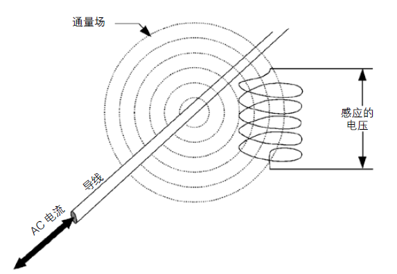
Image sourced from the internet
2. Classification of current probes
At present, the current probes used on oscilloscopes are basically divided into two types: AC current probes and AC/DC current probes. AC current probes are usually passive probes with low cost, but cannot measure DC components. AC current probes have a low-frequency cutoff bandwidth. AC/DC current probes are usually active probes. AC/DC current probes can measure both DC and AC current signals. AC/DC current probes use Hall devices to sense DC and low-frequency AC signals, while high-frequency current signals use the working principle of transformers to sense AC in wires. The bandwidth of current probes can reach several GHz, and commonly used current probes have a bandwidth below 120MHz.
3. Application scenarios of current probes
Current probes are widely used in motor drivers, power supplies, semiconductor devices, power inverters, electronic ballasts, Consumer electronics, motor drivers, etc.
The current probe and voltage probe are tested simultaneously, utilizing the mathematical processing ability of the oscilloscope's Math waveform, which can be used for various power measurements.
Instantaneous power=voltage x current
Effective power=voltage (effective value) x current (effective value) x phase angle
Apparent power=voltage (effective value) x current (effective value)
Voltage angle (phase)
Current angle (phase)
The current detection range of the current probe can range from a few milliamperes to several thousand amperes, and the frequency of the AC/DC current probe can range from DC to over 120MHz. The AC current probe can reach GHz and is widely used for various current measurement needs. The current probe can be selected in a wide range of models according to testing needs. Choosing a current probe for a specific application is similar in many ways to selecting a voltage probe. Sensitivity, current range, frequency range, bandwidth, rise time, AC and DC current capabilities, and other key indicators.
4. Main indicators of current probes
4.1 Bandwidth of current probe
The current probe also has a bandwidth, which refers to the cutoff frequency at which the response amplitude of the probe decreases to -3dB. The AC current probe also has low-frequency bandwidth limitations, and it cannot test DC current and low-frequency current signals. Therefore, the AC current probe has a working frequency range. When using the current probe with an oscilloscope, it is also necessary to consider the bandwidth of the oscilloscope, which determines the overall measurement bandwidth.
4.2 Current probe rise time
The rise time usually uses 10% to 90% Step response time to characterize the conversion time measured by the probe from the front end to the rear end. To * measure the rise time and Fall time, the rise time of the measuring system that requires the combination of oscilloscope and current probe is 3 to 5 times faster than the rise time of the measured signal.
4.3 Ampere second product
For current probes, the ampere second product specifies the maximum limit for linear operation of the current probe. For current pulses, this product is defined as the average current amplitude multiplied by the pulse width. If the product of amperes per second is exceeded, the current transformer core will become saturated. Due to the inability of a saturated magnetic core to handle more current induced flux, there is no longer a constant ratio between current input and voltage output, and the waveform part is clipped in the area exceeding the product of amperes per second; If the product of amperes per second is not exceeded, the signal voltage output of the probe will be linear and the measurement accuracy will be improved.
4.4 High rated input current
The maximum rated input current that the current probe can accept while still operating normally is the total current (DC+peak AC). In AC current measurement, the peak rated value must be reduced based on frequency.
4.5 Large rated peak pulse current
The detection current does not exceed this rated value, taking into account the possibility of secondary voltage accumulation that may damage the equipment due to magnetic core saturation. Large rated peak pulse current is usually specified as the product of amperes per second.
5. Steps for using the current probe
In order to conduct correct current testing, engineers need to demagnetize and zero adjust the current probe before use. Demagnetization can eliminate the parasitic magnetic field of the current probe, otherwise it will cause zero drift and measurement error. After each demagnetization, it is necessary to adjust the zero point of the probe to eliminate any deviation. After the current probe is connected to the channel of the oscilloscope, the ampere unit will generally be automatically displayed on the oscilloscope interface. It is also necessary to click on the AutoZero function menu on the oscilloscope to complete demagnetization and automatic zero calibration. Some current probes have Degauss/AutoZero buttons on the probe, and pressing the AutoZero button will eliminate any DC bias errors in the measurement system.
6. Precautions for using current probes
When selecting a current probe to detect current signals, it is important to pay attention to several main parameters: the size of the current to be measured, current frequency, AC or DC, shape and size of the clamp, power supply method, interface form, etc. Before use, demagnetize and zero calibrate.

TOP


 中
中 EN
EN Current location: