


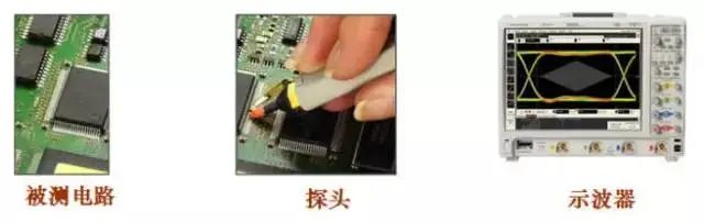
The oscilloscope has expanded its application range due to the presence of probes, allowing it to conduct online testing and analysis of the tested electronic circuit, as shown in the following figure:
The function of the oscilloscope probe
The selection and use of probes need to consider the following two aspects:
Firstly, due to the load effect of the probe, it directly affects the measured signal and circuit;
Secondly, the probe is a part of the entire oscilloscope measurement system, which directly affects the signal fidelity and test results of the instrument.
01. Load effect of the probe
When the probe detects the circuit under test, it becomes a part of the circuit under test. The load effect of the probe includes the following three parts: resistive load effect; Capacitive load effect; Inductive load effect.
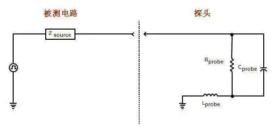
Load effect of the probe
A resistive load is equivalent to connecting a resistor in parallel on the circuit under test, which has a voltage divider effect on the measured signal and affects its amplitude and DC bias. Sometimes, when a probe is added, the faulty circuit may become normal. It is generally recommended that the resistance of the probe R>10 times the measured source resistance to maintain an amplitude error of less than 10%.
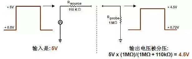
Resistive load of the probe
Capacitive load is equivalent to a capacitor connected in parallel on the circuit under test, which has a filtering effect on the measured signal, affects the rise and fall time of the measured signal, affects the transmission delay, and affects the bandwidth of the transmission interconnection channel. Sometimes, when a probe is added, the faulty circuit becomes normal, and this capacitive effect plays a crucial role. It is generally recommended to use probes with a capacitance load as small as possible to reduce the impact on the edge of the measured signal.
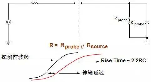
Capacitive load of the probe
The inductive load comes from the inductance effect of the probe ground wire, which forms resonance with the capacitive and resistive loads, causing ringing on the displayed signal. If there is a noticeable ringing on the displayed signal, it is necessary to check and confirm whether it is the true feature of the measured signal or the ringing caused by the grounding wire. The method of checking and confirming is to use the shortest possible grounding wire. It is generally recommended to use a ground wire as short as possible, with a ground wire inductance of 1nH/mm.
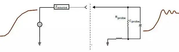
Inductive load of the probe
02. Type of probe
The oscilloscope probes can be divided into two categories: passive probes and active probes. Passive active, as the name suggests, refers to whether the probe needs to be powered or not.
The passive probes are subdivided as follows:
Low resistance resistance voltage divider probe;
High resistance passive probe with compensation (commonly used passive probe);
The active probes are subdivided as follows:
Single ended active probe;
Differential probe;
Current probe
A simple comparison between commonly used high resistance passive probes and active probes is as follows:
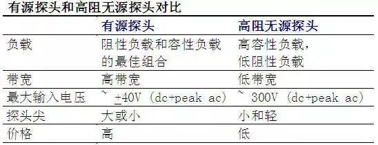
Comparison between active and passive probes
03. Active probe structure
The structure diagram of the differential probe is as follows, and the purpose of impedance transformation is achieved using a differential amplifier. The input impedance of the differential probe is high (usually above 50Kohm), while the input capacitance is small (usually less than 1pf). After being connected to the oscilloscope through the differential probe amplifier, the oscilloscope must use a 50ohm input impedance.

TOP


 中
中 EN
EN Current location: